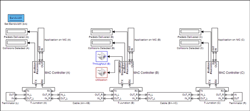
Create Ethernet packet based on the MAC address and EtherType provided: Ethernet Tx: Transmit data over Ethernet network. Learn about Simulink. Try MATLAB, Simulink, and Other Products. Explore Products. MATLAB; Simulink; Student Software. Simulink is a MATLAB-based graphical programming environment for modeling, simulating and analyzing multidomain dynamical systems.Its primary interface is a graphical block diagramming tool and a customizable set of block libraries.It offers tight integration with the rest of the MATLAB environment and can either drive MATLAB or be scripted from it. Simulink is widely used in automatic. Functions and configuration objects for 802.11™ MAC frame generation and parsing WLAN Toolbox™ provides functions to create and parse 802.11 medium access control (MAC) frames. Use these functions to generate and decode control, management, and data frames.
This example shows how to simulate medium access control (MAC) quality of service (QoS) traffic scheduling in 802.11a/n/ac/ax network using SimEvents®, Stateflow®, and WLAN Toolbox™. Using QoS, the MAC layer prioritizes the application data and allocates more resources to high priority traffic compared to low priority traffic. The MAC layer used in this example implements the enhanced distributed channel access (EDCA) algorithm to get access to the channel for transmission. This example models a 802.11 network with five nodes that can be simultaneously configured with four types of application traffic namely: Best-effort, Background, Video and Voice. The type and the priority of application traffic is identified by the access category (AC) at the MAC layer. The derived results show that the highest priority voice traffic incurs the lowest latency, whereas the lowest priority background traffic results in highest latency.
QoS Scheduling in 802.11 Network

The IEEE 802.11 WLAN [ 1 ] standard supports low rate applications and provides best-effort service at the MAC layer. The widespread use of real-time multimedia content along with deployment of time-sensitive critical applications has created a need to provide QoS support in 802.11 networks. To achieve this, the IEEE 802.11 TGe introduced QoS as a part of the IEEE 802.11e amendments to the IEEE 802.11 specification. By providing QoS support, the IEEE 802.11 MAC layer prioritizes the application data and allocates more resources to high priority traffic as compared to low priority traffic.
Simulate QoS Network
This example models a WLAN network with five nodes as shown in this figure. These nodes implement carrier-sense multiple access with collision avoidance (CSMA/CA) with physical carrier sense and virtual carrier sense. The physical carrier sensing uses the clear channel assessment (CCA) mechanism to determine whether the medium is busy before transmitting. Whereas, the virtual carrier sensing uses the RTS/CTS handshake to prevent the hidden node problem.
Each node can be simultaneously configured with these four types of application traffic:
Best-effort (AC0)
Background (AC1)
Video (AC2)
Voice (AC3)

The AC present at the MAC layer identifies the type and the priority of the application traffic.
The MAC layer implements the EDCA algorithm to access the channel for transmission. The EDCA contention parameters are designed such that the high priority traffic gets more transmission opportunities than the low priority traffic. The default configuration assigns priorities to the application traffic in this order: Background, Best-effort, Video and Voice. However, even after using these contention parameters, there is a chance that more than one AC obtains transmission opportunity at the same time resulting in internal collision. If an internal collision occurs:
The high priority AC gets the transmission opportunity
The low priority AC is considered as a transmission failure and invokes a retransmission procedure
This example differs from the 802.11 MAC and Application Throughput Measurement example as multiple applications at the application layer to generate different types of traffic.
Model Configuration
You can configure the application packet size using these steps:
Open model
WLANMACQosSchedulingModel.slxTo go inside a node subsystem, click on the downward arrow at the bottom left of the node
To open mask parameters of the application, double click on
Best Effort ApplicationTo enable application, set
App Stateto 'On'Configure the values of
Packet Size,Packet Interval,Destination NameandAccess categoryUse steps 3, 4 and 5 to configure other applications
For more configuration options, refer 802.11 MAC and Application Throughput Measurement. To add additional nodes in the network, copy and paste any existing node in the network.
Simulation Results
This example generates similar results that are obtained in the 802.11 MAC and Application Throughput Measurement. These results include:
A run-time visualization showing the time spent on channel contention, transmission, and reception for each node. This plot shows MAC state transitions with respect to simulation time.
During the simulation, an optional run-time visualization plot displays the number of frames queued in MAC transmission queues for a selected node. You can observe the run-time state of the MAC layer transmission buffers using the 'Observe MAC queue lengths' button in the above visualization.
A bar graph showing metrics for each node such as number of transmitted, received, and dropped packets at PHY and MAC layers. This plot shows the network statistics at the end of simulation.
A MAT file 'statistics.mat' stores the detailed statistics for each layer and node in the network. Since this example has multiple applications, the MAC layer transmits data packets from different ACs. You can observe the number of transmissions from each AC in 'MACAC0DataTx', 'MACAC1DataTx', 'MACAC2DataTx' and 'MACAC3DataTx' columns of 'statisticsTable' stored in 'statistics.mat'. In a given simulation, the number of transmissions per AC is directly proportional to the priority of the AC.
In addition to the above results, this example shows MAC latencies of all ACs for the selected node in a plot and also creates a MAT file 'macLatenciesLog.mat'. This file contains information about each MAC frame such as:
Entry timestamp: The time at which application packet has arrives at the MAC layer
Node ID: The node ID of the transmitter
AC: Access category of the packet
Clear timestamp: Time at which packet is cleared from the MAC. A packet is cleared from the MAC after successful reception of an acknowledgment or after completing the maximum number of retransmission attempts.
This information is used to calculate MAC latencies per packet. Here, the MAC latency is the time delay between a packet arriving at the MAC from the application layer, and it being cleared from the MAC. A packet is cleared from MAC in these scenarios:
Successful transmission: A receiver sends an acknowledgment to the sender after receiving a packet intended for it. If an acknowledgment is received by the sender, it is considered as a successful transmission.
Packet discard: If an acknowledgment is not received by the sender, it retransmits the packet until the retransmission limit is reached. If an acknowledgment is not received even after completing the maximum number of retransmissions, the packet is discarded at the MAC layer.
The voice traffic has the highest priority and hence incurs the lowest latency. Whereas, the lowest priority of background traffic results in highest latency.
Further Exploration
Configuration options:
In this model, you can configure the MAC contention parameters for each AC. The contention parameters for each AC are stored in 'macConfiguration.mat' as a structure containing three fields namely aifsn, cwMin and cwMax. You can change the priority of the AC (Best-effort/Background/Video/Voice) by changing these contention parameters. You can observe this by enabling multiple applications in a node and changing the contention parameters of the traffic. To change the contention parameters, use this code:
Related examples
Refer these examples for further exploration:
To measure MAC and Application layer throughput in a multi-node 802.11a/n/ac/ax network, refer 802.11 MAC and Application Throughput Measurement example.
To model a multi-node IEEE 802.11ax network with abstracted PHY, refer 802.11ax System-Level Simulation with Physical Layer Abstraction example.
To model a multi-node network using Distributed Coordination Function (DCF) MAC and 802.11a PHY, refer Multi-Node 802.11a Network Modeling with PHY and MAC example.
Matlab Simulink Onramp
This example enables you to configure and simulate MAC QoS traffic scheduling in 802.11 network using a Simulink model for analyzing MAC latencies in each AC. In this model, MAC contention parameters for each AC can be configured to change the application traffic priority at the MAC layer. This example concludes that the voice traffic which has the highest priority, incurs the lowest latency. Whereas, the background traffic that has the lowest priority results in highest latency.
Matlab Simulink Online
Appendix
The helper functions and objects used in this example are:
edcaFrameFormats.m: Create an enumeration for PHY frame formats.
edcaNodeInfo.m: Return MAC address of a node.
edcaPlotQueueLengths.m: Plot MAC queue lengths in the simulation.
edcaPlotStats.m: Plot MAC state transitions with respect to simulation times.
edcaStats.m: Create an enumeration for simulation statistics.
edcaUpdateStats.m: Update statistics of the simulation.
edcaLogLatencies.m: Logs the given information of all frames exchanged in the network.
edcaPlotLatencies.m: Plots the MAC frame latencies in all access category.
helperAggregateMPDUs.m: Aggregate MPDUs to form an A-MPDU.
helperSubframeBoundaries.m : Return subframe boundaries of an A-MPDU.
phyRx.m: Model PHY operations related to packet reception.
phyTx.m: Model PHY operations related to packet transmission.
edcaApplyFading.m: Apply Rayleigh fading effect on the waveform.
heSIGBUserFieldDecode.m: Decode HE-SIG-B user field.
heCPECorrection.m: Estimate and correct common phase error.
heSIGBCommonFieldDecode.m: Decode HE-SIG-B common field.
heSIGBMergeSubchannels.m: Merge 20MHz HE-SIG-B subchannels.
addMUPadding.m: Add or remove the padding difference between an HE-SU and HE-MU PSDU.
macQueueManagement.m: Create a WLAN MAC queue management object.
roundRobinScheduler.m: Create round-robin scheduler object.
calculateSubframesCount.m: Calculate the number of subframes required to form MU-PSDU.
interpretVHTSIGABitsFailCheck.m: Interprets the bits in VHT-SIG-A field
rateAdaptationARF.m: Create an auto rate fallback (ARF) algorithm object.
rateAdaptationMinstrelNonHT.m: Create a minstrel algorithm object.
References
IEEE Std 802.11™. 'Wireless LAN Medium Access Control (MAC) and Physical Layer (PHY) Specifications'. IEEE Standard for Information technology - Telecommunications and information exchange between systems - Local and metropolitan area networks - Specific requirements; LAN/MAN Standards Committee of the IEEE Computer Society